DIY Reradiating GPS Antenna
This page describes modifying a reradiating GPS antenna for use on a GPS which does not have an external antenna adapter. This project came about more as a curiosity to see just what kind of performance can be gained using such an antenna. Two main pages I have used for reference are Heinrich Pfeifer's and Dave Martindale's reradiating antenna pages. I'm also working with Lapaglia, who has already made a similar unit for use with his iPAQ and is impressed with his results. My test dummy - a basic yellow eTrex which has to be one of the most common units used.
- GPS signals are low power, high frequency (1.57542 GHz) digital signals. As long as the GPS is getting a clear signal from a particular satellite, amplifying the signal will do little for your accuracy.
- A reradiating antenna will only amplify signals from satellites that are in view; If the GPS is picking up 4 satellites and all the others are near the horizon, odds are you will only pick up 4 with the reradiating antenna.
- Where the reradiating antenna will help is under heavy cover, where the signal strength is not enough for the GPS to get a clear signal.
The Hardware
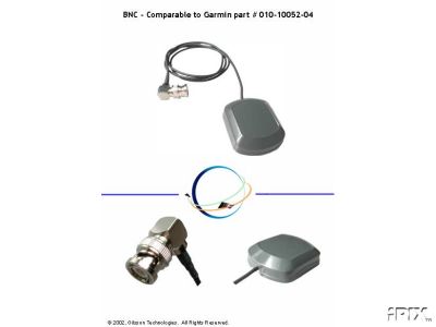
This is the SM-76 amplified antenna I purchased for this project. I found mine on eBay for less than $27 delivered to the door. I was totally deceived by the picture. This is a very small waterproof unit with a magnetic base, measuring about 1.875" X 2.25" X 0.625". This particular unit is available with 3, 9 or 16-feet cable lengths, with the actual unit I bought having the 9 foot cable. The cable is very thin, less than 1/8 inch diameter and terminates in a standard right angle 50 ohm BNC connector. The antenna uses the inner conductor for both the DC power to feed the amplifier as well as for the RF output to drive the transmitting antenna. Stated input power rating is 2.5 - 5 volts with a current draw of 7 mA with a signal gain of 27-33 db typical.

Circuit Design
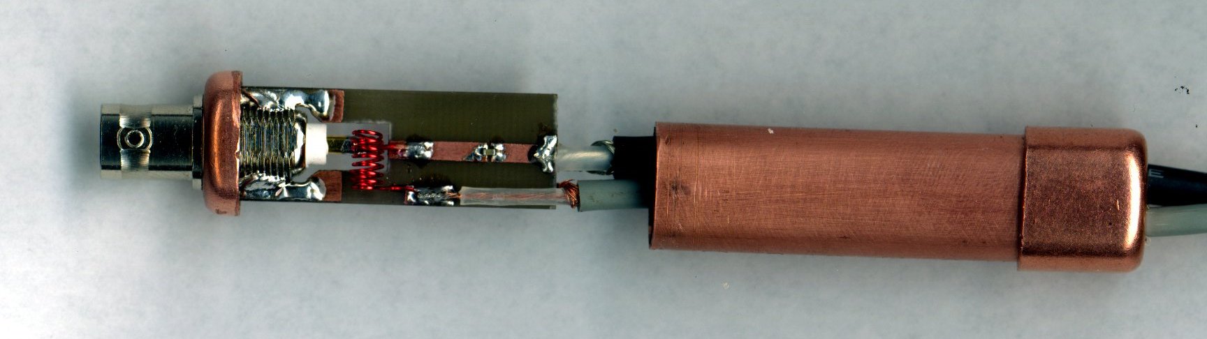
Below is a basic circuit design I put together so I'd have something to play with as soon as the antenna unit got here. Power is supplied by 2 AA batteries, as opposed to the designs from the pages mentioned at the top of this page which get power from a 12 V power source. Using the batteries makes the circuit design much more simple and portable.
Battery power is sent to the center conductor of the BNC jack via a small hand wound inductor. I made this coil by winding 6 turns of #26 AWG magnet wire over a 3/16 drill bit. This inductor acts as an AC block, keeping the RF energy from the amplifier from getting into the power supply. I originally thought this inductor was not necessary since I was running battery power, but without it the RF energy feeds though the batteries causing them to get warm, which we can assume is not a good thing!
The transmitting portion of the circuit consists of 2 parts. A 47pf capacitor which acts as a DC block to the transmitting loop, without it the batteries would effectively be shorted by the low resistance of the transmitting loop. The transmitting antenna loop I am using as a test dummy is 190 mm (one wavelength) of #22 AWG magnet wire. This wire is too flexible for a permanent design, but works well for testing purposes.

Initial Testing
Initial test: In my house. I can typically get a lock inside the house half of the time. It just so happened 12 satellites were "in view" during this test. The basic circuit was used and held about an inch above the GPS.
| Status | Environment | Accuracy |
|---|---|---|
| Amp Off | Indoors (12 Sats) | 32' |
| Amp On | Indoors (12 Sats) | 22' |
Same test, next morning. 7 satellites in view.
| Status | Environment | Accuracy |
|---|---|---|
| Amp Off | Indoors (7 Sats) | 49' |
| Amp On | Indoors (7 Sats) | 25' |
Shielded Enclosure
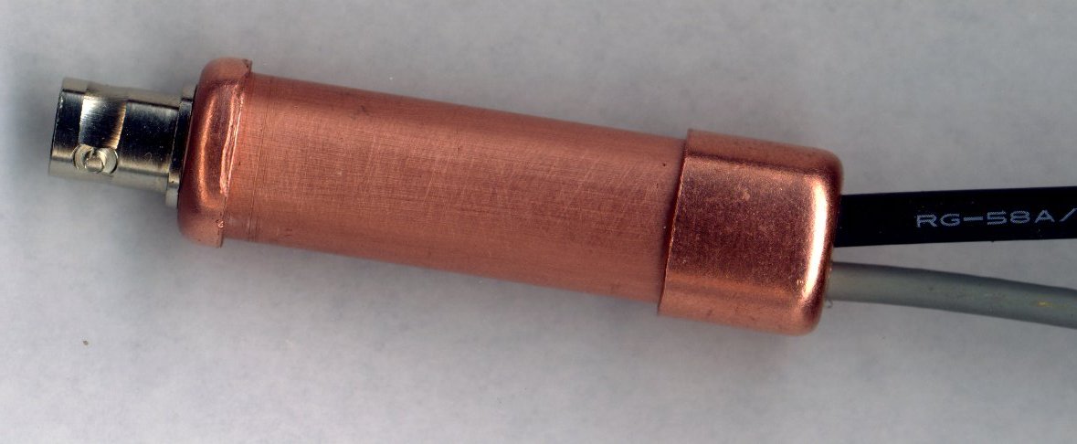
I've decided to build a shielded enclosure and came up with this for a first design. I used a short piece of 1/2 inch copper tubing and 2 end caps, one of which has been shortened to facilitate soldering of the circuit board directly to the BNC connector. The entire assembly is less than 3 inches long, and could be shorter. The second cable is for external batteries, with a longer tubing there would be room for AA batteries, they fit perfectly in the tubing. As an alternative, there is room for button cells inside as-is, and with the low current draw it could be an option. I am using a surface mount capacitor (200pf, smallest I could find) now to keep the impedance down some.
Field Testing
Finally the weather cleared so I made it outside for a test. All day today I have had a good signal, even without the aid of the reradiating antenna, but had to try it out anyway. These results were taken in an open area with a decent view of the sky. The antenna is supposed to work without a ground plane, but for this test I tried it both with and without a ground plane (hood of truck).
| Status | Environment | Accuracy |
|---|---|---|
| Amp Off | Open Area | 23' |
| Amp On | Open Area | 20' |
| Amp On (w/ Ground Plane) | Open Area (Truck Hood) | 17' |
My first use of the antenna at a cache site when the signal was poor. Most of the Satellites were near the horizon, and could only get 3 satellites to lock without the reradiating antenna. I was about 50 feet from the cache without the antenna, and with it got me within 15 feet.
| Status | Environment | Accuracy |
|---|---|---|
| Amp Off | Heavy Cover (Cache Site) | 57' |
| Amp On | Heavy Cover (Cache Site) | 36' |
The Transmitting Antenna (Nichrome Wire Mod)
On to the actual transmitting antenna. The length should be 190 mm as stated before, but that leaves options for different shapes. From what I have read, it's not so much the shape of the loop that makes a difference, it is the area within it. A circle will yield the most area for a shape with a 190mm circumference, about 2874 sq mm; a square loop would yield about 2256 sq mm. However, I have twisted my loop into several shapes and it still seems to work quite well, except for shapes that leave very little area inside. As with all high frequency circuits, very sharp corners and loops should be avoided as it causes higher losses and unwanted inductance.
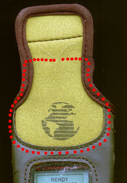
I came up with this brainstorm, tried it out, and it seemed to work as well as the ones I have been using. It is a standard Garmin stretch fit cover with a very fine (35 Gauge, approximately .005") nichrome wire sewn into the center of the skin of the cover. The dotted line shows where the wire runs to make a 190 mm loop. For connectors, I tried nickel plated brass snaps typically used on clothing. Since the nichrome wire is not able to be soldered by conventional means, I wrapped it tightly several turns around one of the loops, then coated it with a conductive ink pen. I then let it dry and coated it with a drop of superglue. For the other connector, I used a small piece of PCB board, drilled two though-holes corresponding to the connectors on the GPS cover, stuck the wires though, placed the other half of the snap and soldered together. I then reinforced the cable with some hot glue on the back side. It seems quite durable and the electrical connection is stable.

Additional Notes Sent By Others:
I read of your experiments with a re-radiating antenna with interest. I'll add my experience. For the antenna itself I used a piece of flexible printed circuit material. This is a very tough film like material with copper on one side. I drew and etched a copper loop. A narrow and long upside down "U" shape with the total length of 190 mm. The open end of the "U" I glued on to the back of a universal mobile telephone holder which in turn is mounted on the car dashboard. I put the Etrex into the phone holder and bend the "U" down over the Etrex internal antenna. I use a Lowe active antenna and a 5v power pack to power the active antenna. Four NI-MH AA battery cells give very close to 5V and can power the active antenna for several weeks.
I let the active antenna lie in the rear car window which gives good results. Satellite lock-on using the patch antenna is fast, usually within a 5 to 15 seconds. Hope my experiences can help others. - Douglas